Why Consistent Traffic Patterns Define Safe Aviation
The traffic pattern is not simply a route leading to a landing. It is an active risk-management corridor where aircraft converge, cockpit workload increases, and small errors in speed, spacing, altitude, or communication can quickly become significant. A disciplined pattern gives every pilot a shared framework for arriving, sequencing, descending, turning, and departing while preserving time for the most important task: seeing and avoiding other aircraft.
Many unstable approaches and pattern conflicts begin with the same weaknesses: an imprecise entry, a wandering track, configuration changes made too late, or radio calls that leave position and intentions unclear. The remedy is not complicated technology. It is standardization. Whether preparing for a safe and orderly CTAF operation or practicing normal landings with an instructor, use exact visual gates, predictable configuration checkpoints, and concise phraseology. A repeatable sequence turns an untowered airport from a source of uncertainty into a calm, manageable operating environment.
Setting the Foundation on Entry and the Downwind Leg
Begin before entering the pattern. Review the airport information, runway in use, traffic pattern direction, published traffic pattern altitude, noise abatement procedures, runway condition, and any local restrictions. The FAA Airplane Flying Handbook explains that pattern procedures vary with wind, obstructions, runway layout, airport characteristics, and local instructions. The standard pattern is normally composed of left turns and is generally flown at about 1,000 feet above airport elevation, but local publications and markings take priority.
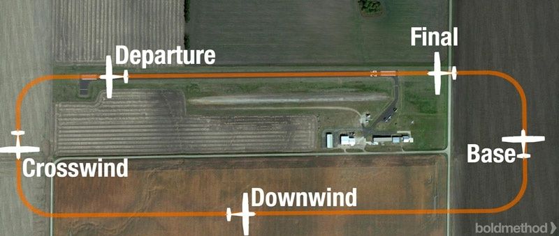
For a conventional arrival, approach the pattern at a safe altitude and enter on a 45-degree angle to the downwind leg at the published traffic pattern altitude. Do not descend into an established flow without a clear reason and a thorough traffic scan. At a non-towered airport, the pilot remains responsible for separation, even when radio calls are being made. Lateral spacing should be consistent enough to provide a useful runway sight picture without placing the aircraft so far away that the base turn becomes excessively long. Depending on the aircraft, runway, and local procedure, a half-mile to one mile abeam the runway centerline is a useful planning range, not a rigid rule.
Once established midfield downwind, stop treating the pattern as a series of improvised turns. Treat it as a sequence of gates that can be briefed, flown, and evaluated.
- Power set: Select the power setting appropriate for the aircraft and pattern speed, while allowing for wind and traffic considerations.
- Altitude and trim: Confirm level flight at the published pattern altitude, then trim so the airplane remains stable without continuous control pressure.
- Configuration review: Complete the pre-landing checklist early enough that it does not compete with traffic scanning during the base and final turns.
- Traffic scan: Look ahead, behind, above, and below. Confirm the runway, identify aircraft in front and behind, and listen for calls that may not correspond to a visible airplane.
- Position confirmation: Check that the aircraft remains parallel to the runway and at the intended lateral spacing before beginning the descent sequence.
Visual Checkpoints and Energy Management from Abeam to Base
The abeam position is normally the point where the landing sequence begins. “Abeam the touchdown point” means the touchdown area is approximately beside the aircraft, not necessarily directly below the wing. At this gate, reduce power according to the aircraft checklist, apply carburetor heat when applicable, lower the nose as needed to maintain the target airspeed, and begin the descent. The first flap extension should follow the aircraft manufacturer”s procedure and the local training standard. Every configuration change affects lift, drag, pitch attitude, visibility, and trim, so make changes incrementally and re-trim after each one.
The 45-degree sight picture is a practical visual reference for timing the base turn. When the runway threshold or intended touchdown area appears approximately 45 degrees behind the wing, the aircraft is often in a useful position to turn base, provided traffic, wind, altitude, and aircraft performance support that decision. This is a visual gate rather than a mechanical trigger. A strong headwind on downwind can move the 45-degree point across the ground quickly, while a tailwind can delay it. Use the sight picture together with the runway track, groundspeed, descent profile, and the location of other aircraft.
Base leg is where many pilots allow energy management to become reactive. The airplane should descend at a controlled rate while maintaining coordinated flight and the selected airspeed. Avoid using pitch alone to stretch a low approach. Raising the nose may appear to preserve the glide path temporarily, but it can cause airspeed to decay and increase the risk of an excessive sink rate or stall. Use the aircraft”s normal pitch-and-power relationship, make small corrections, and keep the final turn in view.
- Keep the turn coordinated with appropriate rudder pressure and a balanced slip-skid indication.
- Do not allow the airspeed to fall below the planned target simply because the runway appears high or distant.
- Use incremental flap deployment within the aircraft”s operating limitations, then re-trim.
- Adjust base spacing for wind and aircraft performance, but avoid large, abrupt corrections close to the runway.
- Continue scanning for traffic throughout the turn, especially beneath the nose and toward the final approach path.
Turning Final and Locking into the Stabilized Approach Window
The final turn should place the airplane squarely on the extended runway centerline with enough distance to establish the landing configuration and assess the approach. Begin the turn with a clear visual reference to the runway, then use coordinated bank and rudder to manage the ground track. If the runway moves toward the outside of the windscreen during the turn, the aircraft may be overshooting. Avoid an aggressive, steep correction that creates excessive bank close to the ground. A go-around or a wider, properly managed circuit is safer than forcing an unstable final.
As the airplane rolls out, verify the runway identity, centerline alignment, landing configuration, airspeed, aiming point, and descent path. The exact targets must come from the aircraft flight manual, operating handbook, and instructor guidance. As a practical training standard, many operators define a stabilized approach by approximately 300 to 500 feet above ground level. By that point, the aircraft should normally be in landing configuration, on the correct lateral path, descending at a controlled rate, and maintaining a constant approach speed toward a defined aiming point. The FAA Airplane Flying Handbook emphasizes a constant-angle glide path, stable configuration, and constant descent airspeed as central features of a stabilized approach.
Use written criteria rather than personal optimism. A landing can look recoverable while still being outside the limits established for safe training or commercial operations. The following comparison helps remove landing bias:
| Stabilized approach condition | Immediate go-around trigger |
|---|---|
| Correct runway alignment and a constant track | Drifting toward the edge, overshooting, or requiring an aggressive correction |
| Landing configuration complete within aircraft limitations | Flaps, trim, or gear configuration incomplete when the stable gate is reached |
| Airspeed within the approved or briefed target range | Significantly fast, slow, or changing despite correction |
| Controlled descent toward the selected aiming point | Excessive sink rate, floating well beyond the aiming point, or a low approach being stretched |
| Runway verified and landing path clear | Uncertainty about runway identity, traffic, surface condition, or runway occupancy |
Standardizing CTAF Communications with Crisp Phraseology
The purpose of a Common Traffic Advisory Frequency is to help pilots build a shared picture of activity at an airport without an operating control tower. CTAF is not a clearance-delivery service and it does not replace visual separation. It supports coordination through accurate self-announced positions and intentions. Before transmitting, listen long enough to understand the existing traffic flow. Monitor the appropriate frequency well before arrival, commonly within about 10 nautical miles, and verify the frequency in current charts, the Chart Supplement, airport information, and NOTAMs.
A useful four-part framework keeps calls concise and complete: identify the facility, identify the aircraft, state position and altitude, state intentions, then repeat the facility name. For example, an arrival call might be structured as: “Lakeview traffic, Cherokee Four Five Six Seven, ten miles west, two thousand five hundred feet, inbound for landing runway Two Seven, Lakeview.” Once established in the pattern, calls should describe the aircraft”s actual location rather than narrate every cockpit action.
- Use the published airport name, not a local nickname that another pilot may not recognize.
- State the runway number and use clear geographical references such as “left downwind,” “base,” or “final.”
- Include altitude when it adds useful traffic information, especially during arrival and transition.
- Transmit before entering the pattern, on significant pattern legs, before taking the runway, and after departing or vacating the runway as appropriate.
- Avoid “any traffic in the area, please advise.” Make a specific position and intention call instead.
- Keep the microphone time short. A long narrative can block a more urgent traffic call.
Radio discipline is most effective when paired with visual discipline. A clear call does not prove that the runway is clear, and a silent aircraft may still be present. If a call conflicts with what is visible, give priority to collision avoidance, continue scanning, and adjust the plan. The FAA”s Aeronautical Information Manual guidance reinforces the need for pilots at airports without operating towers to monitor, communicate, and exchange traffic information while remaining alert to the limitations of self-announced operations.
Take Discipline and Precision into Your Next Flight
Consistent pattern flying comes from replacing guesswork with defined gates. Brief the entry altitude and direction, establish predictable spacing, set power and trim on downwind, begin the descent abeam the touchdown point, use the 45-degree sight picture for base timing, and arrive on final with the landing configuration complete. These numbers and visual references do not eliminate judgment. They give judgment a reliable framework, allowing deviations to be recognized early rather than explained away late.
Before the next flight, agree with the instructor or operating handbook on the aircraft”s target speeds, flap schedule, stabilized approach altitude, maximum acceptable descent rate, and go-around criteria. Apply the same mental model at every airport while respecting local procedures, runway restrictions, traffic direction, wind, and aircraft-specific limitations. If airspeed, alignment, configuration, runway verification, or traffic separation does not meet the briefed standard, execute the go-around promptly. A missed approach in the pattern is not a failure of the procedure. It is the procedure working exactly as intended.